Coordinated 3-tier low voltage power architecture from primary intake to final circuits
Modern facility electrical networks require a systematic three-tier distribution topology to ensure high power reliability, operational safety, and full fault discrimination. Power cascades progressively through Main Distribution Boards (MDB), Sub-Distribution Boards (SDB), down to Final Distribution Boards (FDB).
This architecture ensures that high prospective short-circuit currents are handled safely at primary cubicles, while intermediate and branch circuits benefit from targeted isolation, zone metering, and touch-safe maintenance.
 Tier 1 • Primary Intake
Primary intake from utility transformers or standby gensets (800 A – 6300 A). Fully design verified to IEC 61439-1 & 2 for 50°C ambient operation with Form 4b physical segregation and 50 kA / 3s to 100 kA / 1s ASTA fault ratings.
 Tier 2 • Intermediate Zone
Floor or zone-level power splitting (125 A – 800 A). Wall-mounting and pedestal sheet steel assemblies providing 4 to 18 triple-pole outgoing ways, side cableways, and add-on DIN96 digital energy metering.
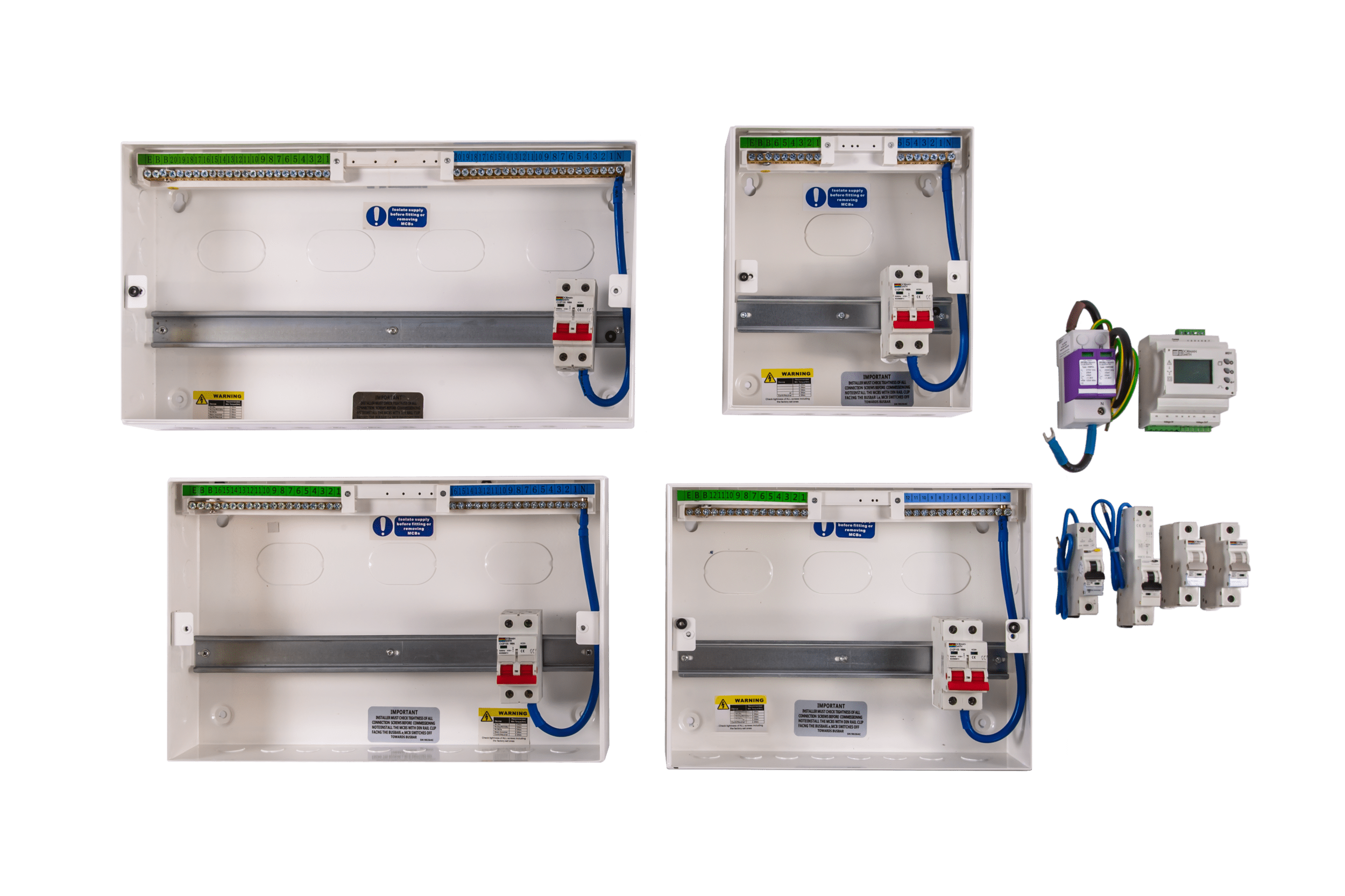 Tier 3 • Final Branch
End-point consumer units and row-type boards supplying lighting circuits, socket outlets, and small appliances (10 A – 250 A) with 30 mA RCBO/MCB shock protection and split-busbar configurations.
| Hierarchy Level | Role & Intake | Current Rating | Fault Withstand | Separation |
|---|---|---|---|---|
| Tier 1: MDB Main Distribution Switchboard | Primary intake from utility transformers or standby gensets. Feeds major plant and SDB risers. | 800 A – 6300 A | 50 kA – 100 kA / 1s (50 kA / 3s) | Form 2b to Form 4b (Type 2 to 7) |
| Tier 2: SDB Sub-Distribution Switchboard | Intermediate floor, departmental, or wing level. Isolates local zones and balances phases. | 125 A – 800 A | 25 kA – 50 kA / 1s | Form 2 standard, Form 4 available |
| Tier 3: FDB Final Distribution Board | End-point consumer unit feeding lighting, power sockets, HVAC terminal units and appliances. | 10 A – 250 A | 6 kA – 17 kA / 250ms | Form 1 to Form 2 (IP41 / IP54) |
| Parameter | MDB Technical Specification |
|---|---|
| Standards & Verification | IEC / BS EN 61439-1 & 2, certified by ASTA / KEMA |
| Ambient Temperature | Fully design verified for operation at 50 °C ambient |
| Enclosure Construction | 2.0 mm – 2.5 mm welded/bolted frame, 1.6 mm – 2.0 mm covers, RAL 7035 finish |
| Busbar System | 4-pole with fully rated neutral, HDHC tin-plated copper (1250 A – 6300 A) |
| Incoming Devices | Withdrawable / Fixed 3-pole and 4-pole Air Circuit Breakers (ACB) up to 6300 A |
| Outgoing Devices | Fixed / Plug-in MCCBs up to 800 A, Fuse-Switch Combination Units (AC23A to 80 kA) |
| Power Monitoring | True RMS multi-function digital power analysers, THD monitoring, Modbus/Ethernet |
| Parameter | SDB Technical Specification |
|---|---|
| Standards & Verification | IEC / BS EN 61439-2, ASTA certified |
| Mounting & Enclosure | Wall mounting and pedestal sheet steel assemblies (1.2 mm – 1.6 mm steel) |
| Incomer Capacities | 250 A, 400 A, and 800 A MCCB or Switch Disconnector |
| Outgoing Ways | 4 to 18 triple-pole outgoing ways accommodating MCCB frames up to 250 A |
| Modular Add-Ons | Cable spreader boxes, side cableways, metering door kits, and service centers |
| Surge Protection | Integrated Type 1 Class I and Type 2 Class II surge suppression kits |
| Parameter | FDB Technical Specification |
|---|---|
| Standards & Verification | IEC / BS EN 61439-3, ASTA certified |
| Configurations | SP&N Consumer Units, TPN Vertical Boards (4–16 way), Horizontal Row Type DBs (1–6 rows) |
| Incomer Options | 63 A – 250 A double-pole/four-pole Switch Disconnectors, RCCBs, or MCCBs |
| Outgoing Devices | 1P, 2P, 3P MCBs (B, C, D curves 6 A – 63 A), 30 mA RCBOs and RCCBs |
| Busbar Construction | 100 A – 250 A hard-drawn high-conductivity tin-plated copper (ETP Grade C101) |
Talk to our switchgear engineering team about single-line diagrams, cascading studies, and custom panel lineups.