
Distribution Hierarchy: MDB, SDB & FDB
Coordinated 3-tier low voltage power architecture from primary intake to final circuits
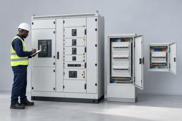
The 3-Tier Power Distribution Hierarchy
A distribution hierarchy groups the primary intake, floor or zone feeders and final circuits into appropriate assemblies. Main distribution boards (MDBs), sub-distribution boards (SDBs) and final distribution boards (FDBs) perform different roles; their current ratings can overlap between projects.
Select each tier from the load schedule, cable routes, prospective fault current and required access. Verify protective-device selectivity with the manufacturer’s coordination data; neither a three-tier layout nor a reference photograph guarantees full discrimination.
The Three Distribution Tiers
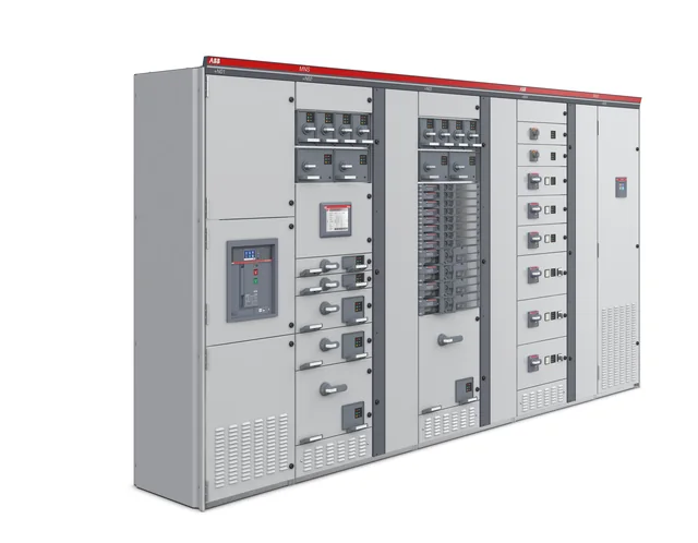
Main Distribution Switchboards (MDB)
ABB MNS Digital is pictured as a primary-intake and motor-control lineup reference. NPE project assemblies are specified from the load schedule, prospective fault current and operating conditions; the photograph does not establish a particular current, fault or separation rating.
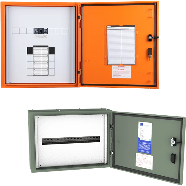
Sub-Distribution Switchboards (SDB)
The NHP Concept Plus family shows a wall-mounted panelboard with its accessory enclosure, suitable as a sub-distribution reference. This Australian AS/NZS 61439-3 range has isolator incomers up to 250 A or MCCB incomers up to 200 A; it is not a Form 4 main-switchboard lineup.
Explore Sub-Distribution Switchboards (SDB)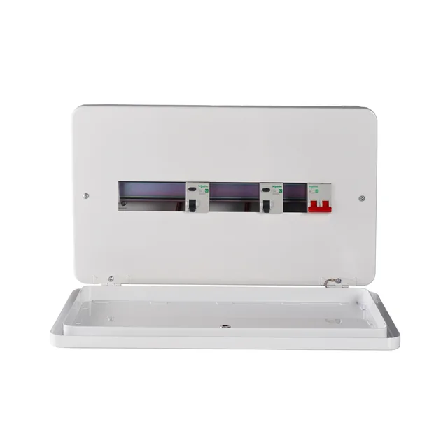
Final Distribution Boards (FDB) & Consumer Units
The Schneider Electric Easy9 EZ9EFS12CMCU is a 12-way single-phase metal consumer-unit reference for final circuits. MCB, RCD and RCBO selection, loading and enclosure configuration must be confirmed for the actual board.
Explore Final Distribution Boards (FDB) & Consumer UnitsHierarchy Tier Specifications
| Selection item | Engineering requirement |
|---|---|
| MDB · primary intake | Main incomer and feeders; determine assembly current, fault withstand and separation from the project. ABB MNS is a lineup reference. |
| SDB · floor or zone | Distributes selected outgoing feeders. Pictured NHP panelboard family is not an 800 A / Form 4 assembly. |
| FDB · final circuits | Feeds lighting, sockets and equipment through selected MCBs / RCBOs. Pictured Easy9 is a single-phase consumer unit. |
Tier 1 — Main Distribution Boards (MDB)
| Selection item | Engineering requirement |
|---|---|
| Assembly standard | Determine the applicable IEC 61439 part and obtain design-verification and routine-verification records for the supplied assembly. |
| Current and voltage | From the approved load schedule, diversity, supply arrangement and service conditions. |
| Short-circuit performance | Prospective fault current, duration, protective-device coordination and assembly verification must agree. |
| Separation and access | Specify the required form and maintenance method. Internal separation does not authorise live work. |
| Enclosure and ambient | Specify IP rating, location, ventilation, temperature rise and cable access for the actual installation. |
| Photographs | Manufacturer references illustrate equipment classes; ratings are not inferred from appearance. |
Tier 2 — Sub-Distribution Boards (SDB)
| Selection item | Engineering requirement |
|---|---|
| Reference family | NHP Concept Plus wall-mounted panelboards, AS/NZS 61439-3 |
| Reference incomers | Isolator up to 250 A; MCCB incomer up to 200 A, subject to exact configuration |
| Project SDB | Select pole count, outgoing ways, loading, metering and fault performance independently. |
Tier 3 — Final Distribution Boards (FDB)
| Selection item | Engineering requirement |
|---|---|
| Reference | Schneider Electric Easy9 EZ9EFS12CMCU, 12-way single-phase consumer unit |
| Final circuits | Choose device current, trip curve, pole count, residual-current protection and breaking capacity per circuit. |
| MCB vs RCD | An MCB provides overcurrent protection; use the specified RCD or RCBO for residual-current protection. |
Advantages of Coordinated Hierarchy
- Selectivity: Verify downstream and upstream device coordination against manufacturer tables and the fault study.
- Safety & Segregation: High energy busbars stay isolated in primary plant rooms under Form 4 barriers, while final user boards are touch-safe.
- Scalable Expansion: Add-on cableways, spare outgoing ways, and modular enclosures allow plant expansion without redesigning main switchboards.
- Granular Metering: Energy sub-metering at SDB and FDB levels enables ISO 50001 energy accounting and departmental billing.
Typical Applications
Engineer Your Complete Distribution Scheme
Talk to our switchgear engineering team about single-line diagrams, cascading studies, and custom panel lineups.
Explore your requirements.
Try the tools relevant to distribution hierarchy: mdb, sdb & fdb, compare scenarios, then send the inputs to our team.
Enable JavaScript for live calculations, or ask our engineering team.
Connect your application to the right components.
Explore these related component families, compare exact manufacturer references and build a quotation request.
LOVATO manufacturer family images; exact configurations vary by model.
Send a BOQ or parts list