
Steady inductive load
Consider fixed correction only after checking the load profile and switching arrangement.
SOLUTIONS / APPLICATION GUIDE
Start with measured demand, power factor and harmonics. Compare correction options and prepare a clear brief for your site.
Enable JavaScript for interactive estimates or ask our engineering team.
CHOOSE YOUR APPROACH
Consider fixed correction only after checking the load profile and switching arrangement.
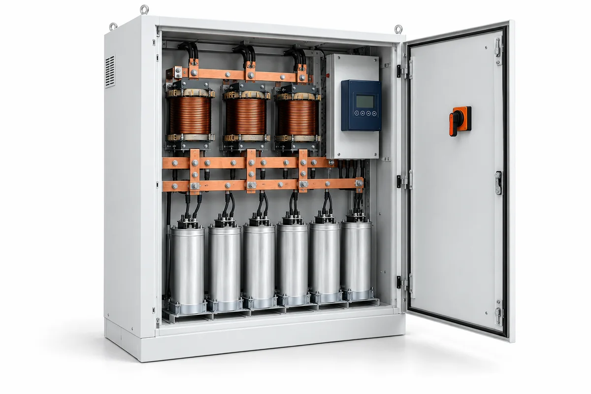
Review an automatic stepped bank against minimum load and required response.
Measure harmonics before choosing detuned correction or active filtering.
BUILD A USEFUL BRIEF
No. Correction changes reactive demand; savings depend on your tariff, measured load and existing equipment. Do not assume an energy-saving percentage.
COMPONENTS THAT COMPLETE THE APPLICATION
Start with the equipment duty. Add the control, protection and measurement functions that your project needs; these are options to review, not a pre-approved assembly.
Images are AI-generated illustrations of equipment categories, not LOVATO model photographs. Confirm dimensions and ratings from the selected model datasheet.
Energy management
Review stepped or fast correction control against the load profile.
Confirm: Number of steps · CT arrangement · harmonic conditions.
Compare selection details ↗
Energy management
Measure demand and energy at useful points in the system.
Confirm: Measured circuits · accuracy needs · data integration.
Compare selection details ↗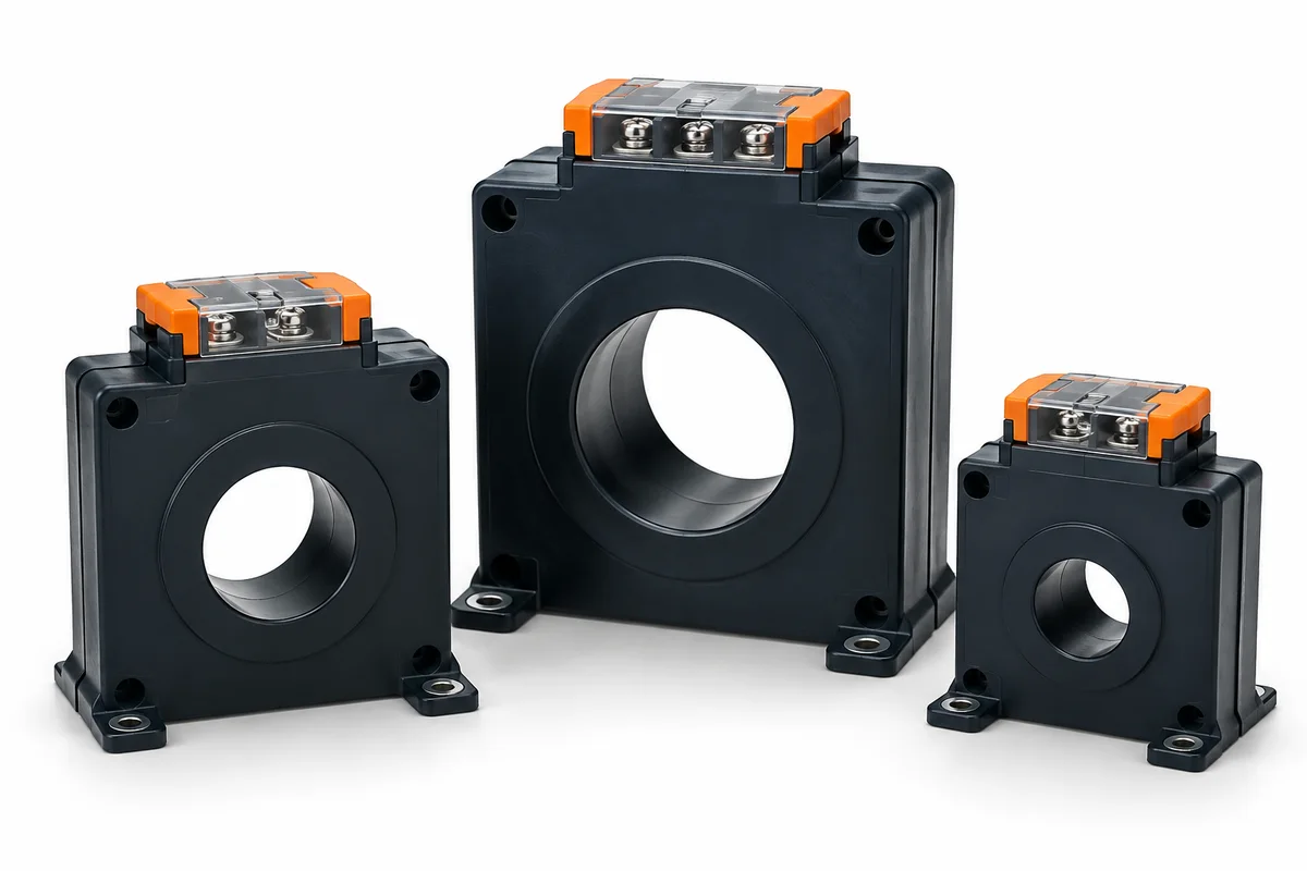
Energy management
Match sensing to the meter or protection application.
Confirm: Ratio and secondary · class and burden · conductor aperture.
Compare selection details ↗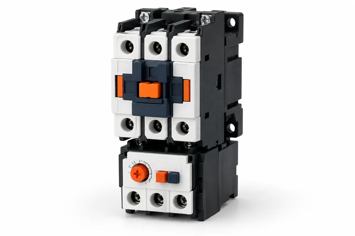
Motor protection & control
Switch motors or other loads using the appropriate utilisation category.
Confirm: Load type and duty · coil supply · auxiliary contacts.
Compare selection details ↗Energy management
Connect compatible devices to the required monitoring network.
Confirm: Protocol · physical interface · network architecture.
Compare selection details ↗Explore all 36 component families ↗
METHODS & WORKED EXAMPLES
These examples use the default inputs. Change the live controls above for your own scenario; the reference examples below remain fixed.
Required kVAr = active kW × [tan(arccos(current power factor)) − tan(arccos(target power factor))].
Technical reference: Schneider Electric: power-factor correction selection. This reference does not certify the website calculation or an NPE assembly.