
Earthing and residual-current protection
Identify the actual earthing system and fault path before choosing residual-current protection.

Decisions before procurement
| Decision | What to establish | Evidence to bring |
|---|---|---|
| Earthing arrangement | Confirm TT, TN or IT and document bonding and the source earth arrangement. | Single-line diagram and measured electrode/loop data |
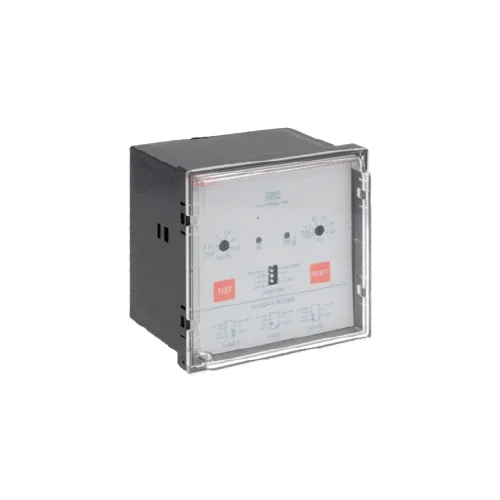
| Device duty | Match sensitivity, delay and RCD type to the load and coordination requirements. Drives and DC leakage affect device choice. | Load type, leakage measurements and adjacent devices |
| Verification | The TT voltage constraint is only one condition. Verify disconnection time, bonding and additional protection separately. | Inspection and test results |
Your project brief
- Earthing system and electrode/loop test results
- Drives, UPS, EV and other electronic loads
- Existing devices and nuisance-trip history
- Applicable protection and coordination requirements
Confirm the actual supply and control voltage. Kenyan projects commonly specify 230/240 V single-phase or 400/415 V three-phase; the selected equipment must match the measured supply and manufacturer rating.
Engineering methods
Related guides
Choose a reference or send your BOQ
Compare relevant product families, then confirm the exact rating, control supply and duty. Price and availability are confirmed with your enquiry.

Technical references
These references support planning. The exact model documentation and a project-specific engineering review govern the final specification.