No. The calculator uses your explicit scenario assumption. A project engineer must establish permitted diversity and utility requirements for the actual development.
Start with the equipment duty. Add the control, protection and measurement functions that your project needs; these are options to review, not a pre-approved assembly.
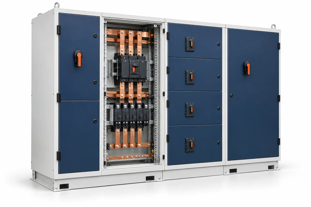
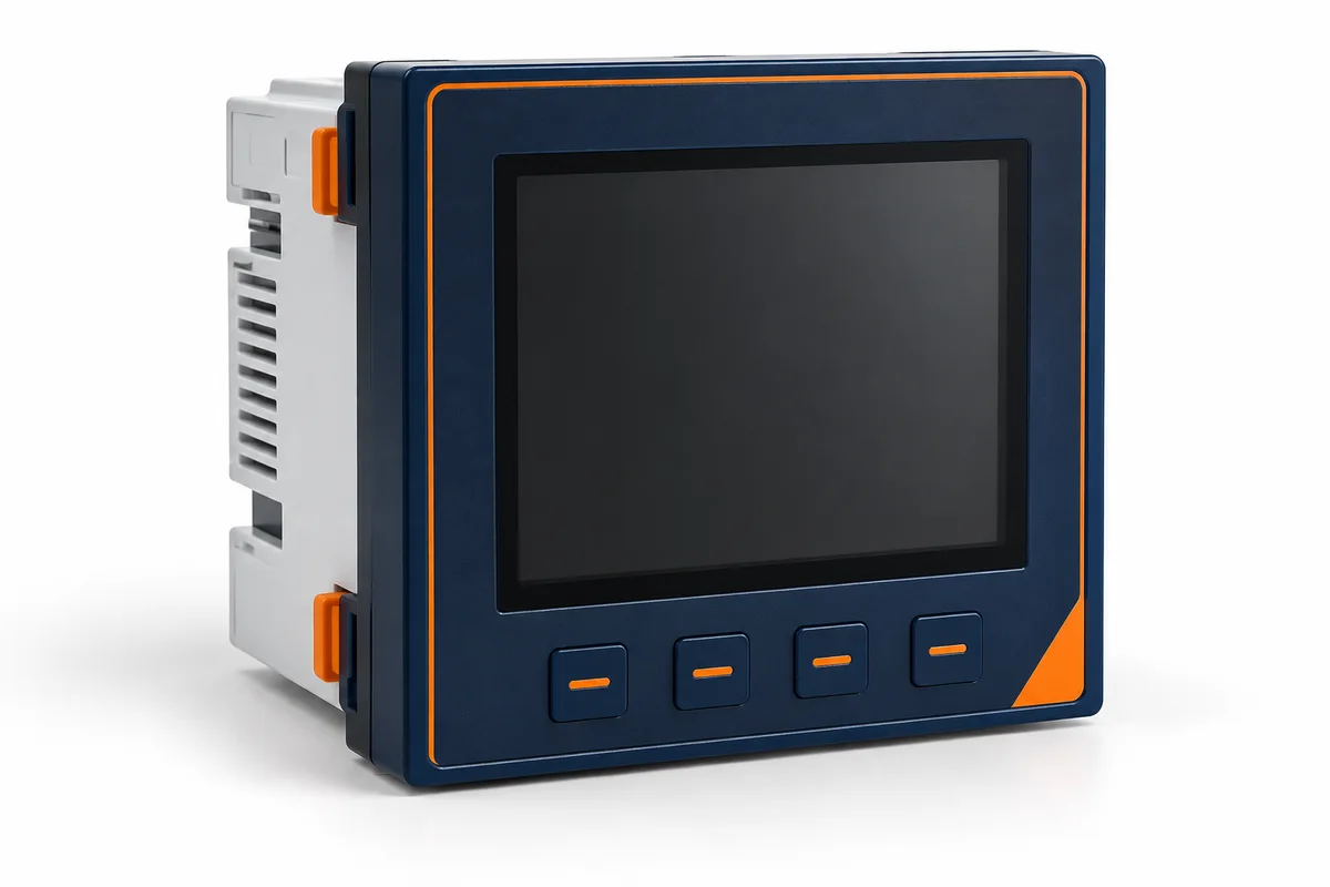
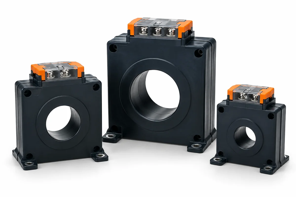
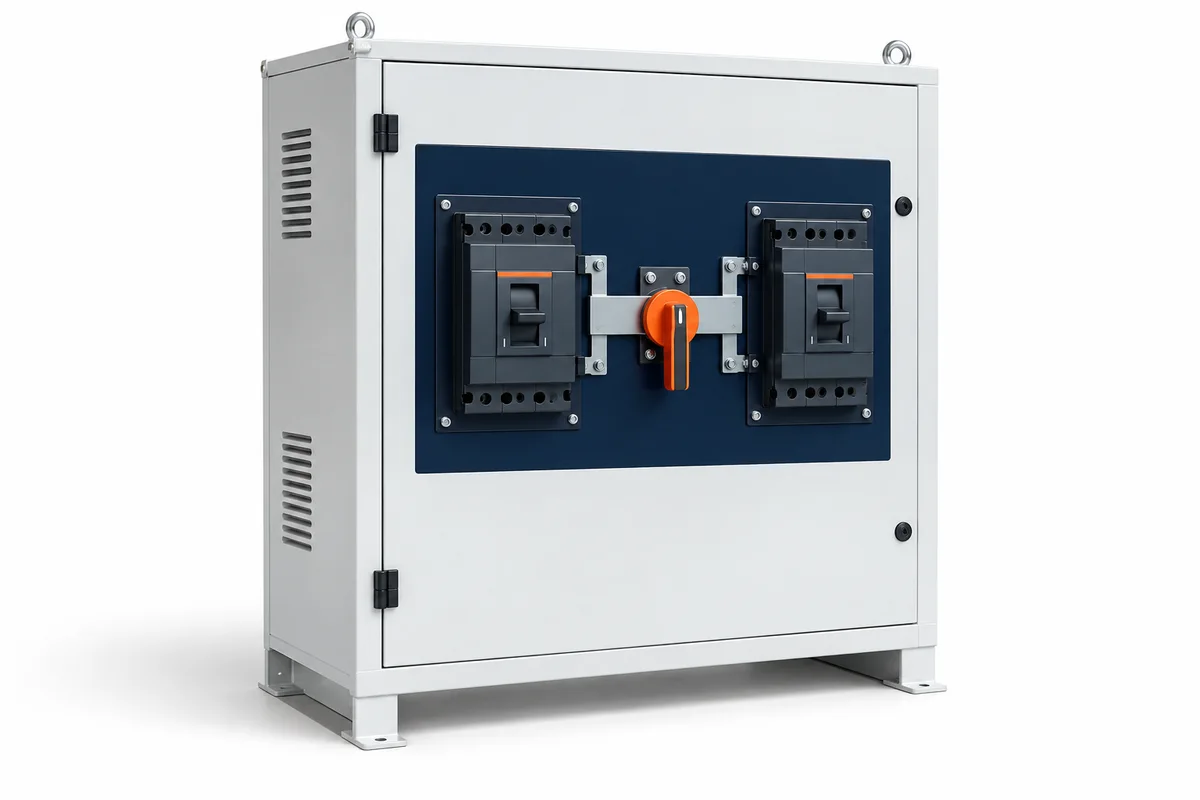
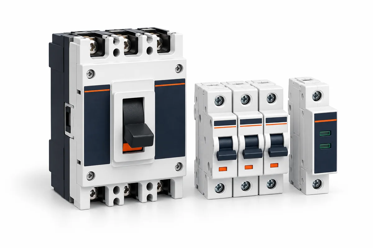
Images are AI-generated illustrations of equipment categories, not LOVATO model photographs. Confirm dimensions and ratings from the selected model datasheet.
Generator: 350 kVA prime/standby, 3Φ balanced at 415 V
Design power factor: 0.8
Step load acceptance should be confirmed against the alternator curve
Nairobi sits near 1,700 m, so altitude derating is applied by default.
Preliminary planning only. Final selection needs project-specific engineering verification.
Solar PV sizing — worked example
Example inputs
Simultaneous peak AC load: 5 kW
AC load power factor: 0.9
Daily consumption: 12 kWh
Peak sun hours: 5.5 h
Panel wattage: 550 W
Days of autonomy: 1
Inverter: 1Φ (single phase)
Storage chemistry: Lithium — 85 % usable
Example result
Array size: 2.8 kWp
Panels required: 6
Indicative inverter class: 8 kVA
Assumptions & limits
Hybrid inverter: 8 kVA, 1Φ single phase
System losses assumed: 22 % (soiling, temperature, wiring)
Peak sun hours: 5.5 h/day
Inverter class considers entered simultaneous peak load and load power factor. Verify motor surge, overload duration, PV input limits and manufacturer ratings separately.
Preliminary planning only. Final selection needs project-specific engineering verification.
Glare: keep UGR below 19 for office and screen-based work
Preliminary planning only. Final selection needs project-specific engineering verification.
METHODS & WORKED EXAMPLES
Understand the estimate.
These examples use the default inputs. Change the live controls above for your own scenario; the reference examples below remain fixed.
Managed EV charging capacity — worked example
Example inputs
Connected charge points: 8
Maximum power per charge point: 7.4 kW
Site active-power limit: 100 kW
Other simultaneous site demand: 60 kW
Configured EV power cap: 30 kW
Example result
Connected charging power: 59.2 kW
Site headroom: 40 kW
Managed EV allocation: 30 kW
Assumptions & limits
EV allocation = min(connected power, max(0, site limit − other demand), configured EV cap).
All limits are active power in kW, not kVA. The equal-share illustration assumes every connected point requests power.
This is a snapshot: building demand and vehicle acceptance change over time.
Verify phase loading, minimum charging current, metering, controller communications and fail-safe behaviour. A low allocation may require queued or paused sessions; it does not guarantee every vehicle can charge.
This does not size cables, protection, service capacity or certify charger compatibility.
Preliminary planning only. Final selection needs project-specific engineering verification.