SOLUTIONS / APPLICATION GUIDE
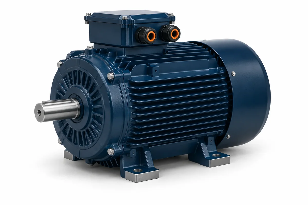
Electric motors Match the motor to its load, mounting and duty. Compare energy use using your operating hours and tariff before considering a replacement.
AI-generated equipment illustration. CHOOSE YOUR APPROACH
Start with the application. Like-for-like replacement Check frame, shaft, flange, speed, voltage and mounting dimensions before ordering.
Long running hours Compare efficiencies at the actual load, alongside installed cost and downtime.
Drive-fed applications Check insulation, bearing protection, cooling and the permitted speed range.
BUILD A USEFUL BRIEF
Bring these details. Clear nameplate and mounting photographs Rated kW, rpm, voltage, current and duty Frame, shaft and flange dimensions Load profile, hours, ambient temperature and ingress protection Send your project brief ↗ Is matching kW enough for a replacement? No. Speed, torque, mounting, supply, starting method, duty and environmental requirements must also match.
← Explore all application hubs
COMPONENTS THAT COMPLETE THE APPLICATION
Specify the whole working system. Start with the equipment duty. Add the control, protection and measurement functions that your project needs; these are options to review, not a pre-approved assembly.
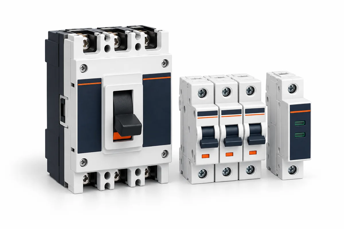
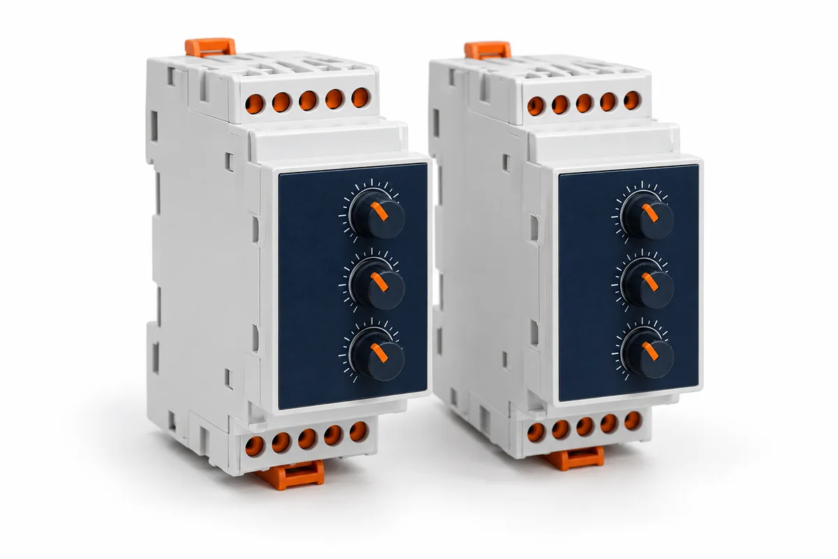
Images are AI-generated illustrations of equipment categories, not LOVATO model photographs. Confirm dimensions and ratings from the selected model datasheet.
Motor protection & control
Protect individual motor circuits as part of a coordinated starter.
Confirm: Motor full-load current · fault level · starter coordination.
Compare selection details ↗ Motor protection & control
Monitor overload conditions within the motor protection scheme.
Confirm: Motor current · trip class · reset strategy.
Compare selection details ↗ Automation & control
Identify phase, voltage or current conditions that need an alarm or trip.
Confirm: Monitored quantity · operating window · reset behaviour.
Compare selection details ↗ Isolation & protection
Plan an appropriate isolation point for equipment and maintenance.
Confirm: AC or DC duty · pole arrangement · locking requirements.
Compare selection details ↗ Explore all 36 component families ↗
METHODS & WORKED EXAMPLES
Understand the estimate. These examples use the default inputs. Change the live controls above for your own scenario; the reference examples below remain fixed.
Motor energy comparison — worked example Annual kWh = rated shaft kW × load fraction × annual hours / efficiency fraction. Cost difference uses the entered energy tariff.
Example inputs Rated shaft power: 30 kW Shaft load: 75 % Existing efficiency at duty: 88 % Replacement efficiency at duty: 93 % Annual running hours: 4000 h Energy tariff assumption: 25 KES/kWh Installed replacement cost: 150000 KES Example result Existing annual energy: 102,272.7 kWh Replacement annual energy: 96,774.2 kWh Annual cost difference: 137,463 KES Assumptions & limits Both motors deliver the same shaft duty. Use efficiency at this load, not an unrelated nameplate point. Tariff is your scenario input, not a published utility rate. Simple payback excludes finance, maintenance, downtime and tariff changes. Negative difference means higher operating cost. Preliminary planning only. Final selection needs project-specific engineering verification. Technical reference: US Department of Energy: motor systems guide . This reference does not certify the website calculation or an NPE assembly.
Motor starting current — worked example Example inputs Motor rating: 55 kW System voltage: 415 V — industrial Phase: 3Φ (three phase) Starting method: Direct on line (DOL) Efficiency: 92 % Power factor: 0.86 Example result Full load current: 96.7 A Starting current: 580 A Starting multiplier assumption: 6 × FLC Assumptions & limits Starting multipliers are illustrative, not measured inrush or guaranteed torque. Verify motor nameplate, load acceleration, supply limits and starts per hour. Preliminary planning only. Final selection needs project-specific engineering verification. Geared motor speed & torque — worked example Output speed = motor rpm / reduction ratio. Output torque (Nm) = 9550 × output shaft kW / output rpm.
Example inputs Motor shaft power: 4 kW Motor speed: 1500 rpm Reduction ratio: 30 :1 Gear efficiency: 90 % Service factor assumption: 1.5 Example result Output speed: 50 rpm Output torque: 687.6 Nm Rated torque requirement: 1,031.4 Nm Assumptions & limits n₂ = n₁ / ratio; T₂ = 9550 × output kW / output rpm. Service factor increases the required gearbox rating, not available torque. Verify thermal capacity, peak torque, shock, mounting and shaft loads with the manufacturer. Preliminary planning only. Final selection needs project-specific engineering verification. Technical reference: SEW-EURODRIVE drive selection guide . This reference does not certify the website calculation or an NPE assembly.
METHODS & WORKED EXAMPLES
Understand the estimate. These examples use the default inputs. Change the live controls above for your own scenario; the reference examples below remain fixed.
Three-phase voltage unbalance — worked example Example inputs L1–L2 voltage: 415 V L2–L3 voltage: 410 V L3–L1 voltage: 420 V Example result Average line voltage: 415 V Maximum deviation: 5 V Voltage unbalance: 1.2 % Assumptions & limits Unbalance (%) = 100 × maximum absolute deviation from the average / average. Use line-to-line readings taken under the same operating condition. No pass/fail limit or trip delay is selected. Check equipment limits and investigate supply conditions with a qualified engineer. This method uses voltage magnitudes only; it is not an IEC negative-sequence calculation. Preliminary planning only. Final selection needs project-specific engineering verification. Method reference: US DOE — Energy Management for Motor-Driven Systems