SOLUTIONS / APPLICATION GUIDE
Motor controls & automation Compare starting methods around the machine, supply and operating sequence. Plan control, protection and commissioning together.
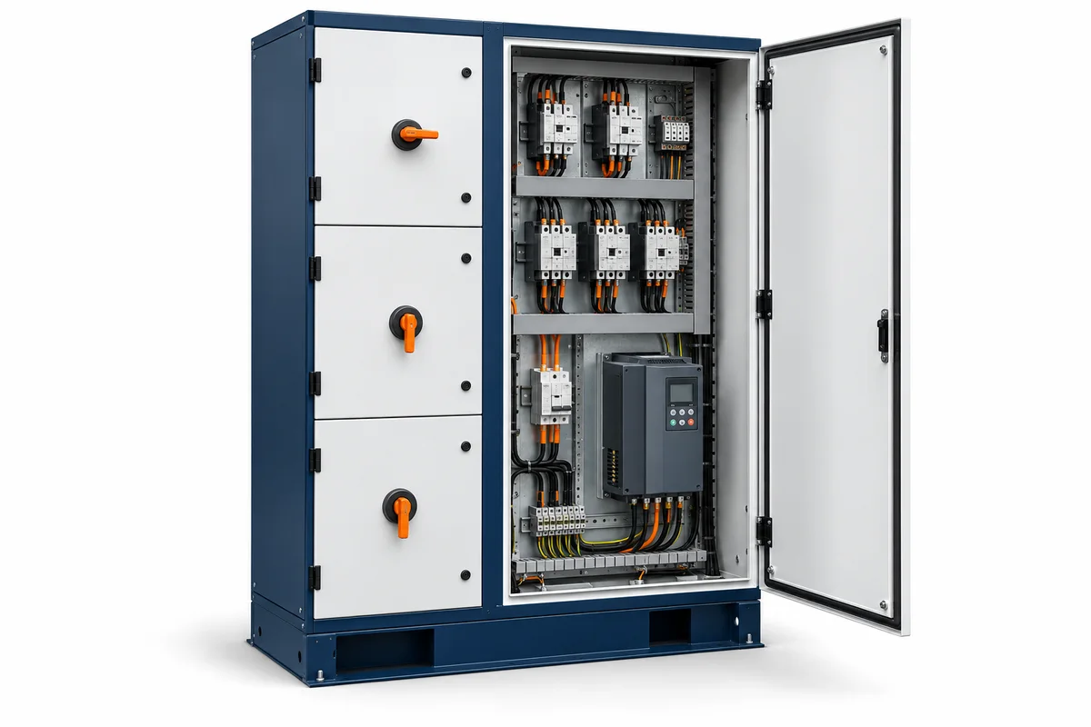
AI-generated equipment illustration. CHOOSE YOUR APPROACH
Start with the application. Fixed speed, simple sequence Review DOL or star-delta starting against supply limits and machine acceleration.
Controlled acceleration A soft starter may suit a fixed-speed duty; starting torque and thermal limits still matter.
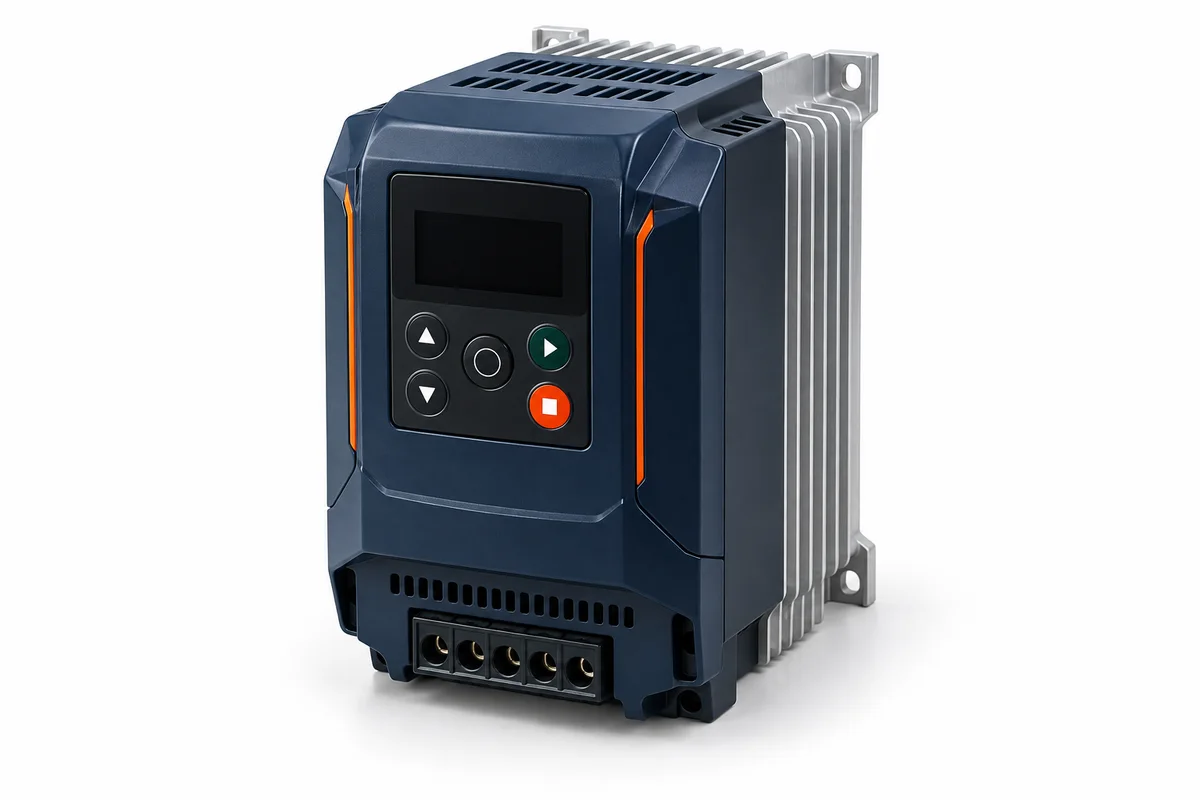
Variable process demand A VFD can control speed. Review motor compatibility, harmonics, cooling and cable length.
BUILD A USEFUL BRIEF
Bring these details. Motor nameplate, voltage and full-load current Driven machine, torque profile and starts per hour Control voltage, interlocks and emergency-stop requirements Cable length, environment and supply capacity Send your project brief ↗ Can any motor use star-delta starting? No. It needs a suitable three-phase motor, accessible winding terminals and a voltage rating compatible with delta operation on the supply. Verify the nameplate and load torque.
← Explore all application hubs
COMPONENTS THAT COMPLETE THE APPLICATION
Specify the whole working system. Start with the equipment duty. Add the control, protection and measurement functions that your project needs; these are options to review, not a pre-approved assembly.
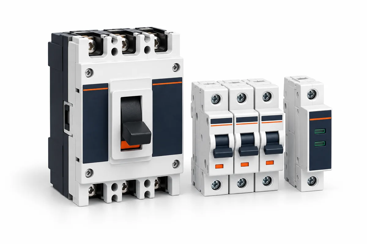
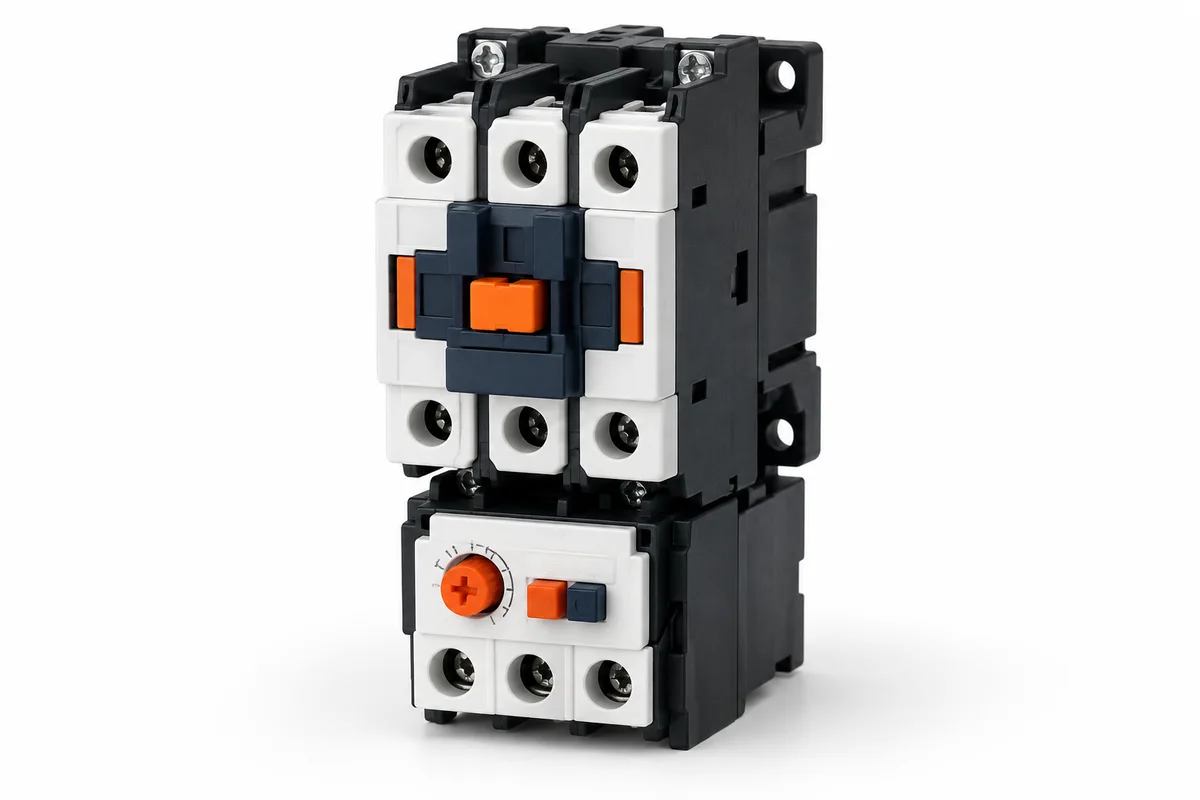
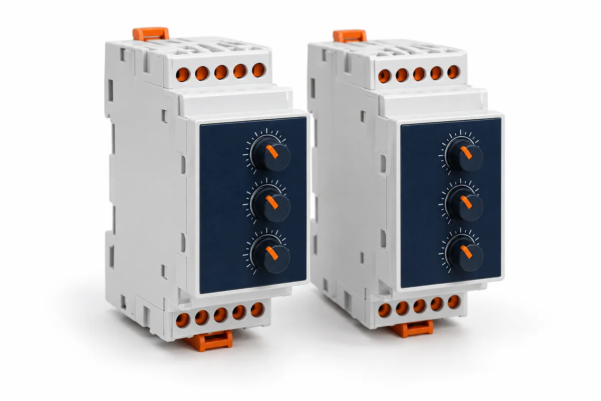
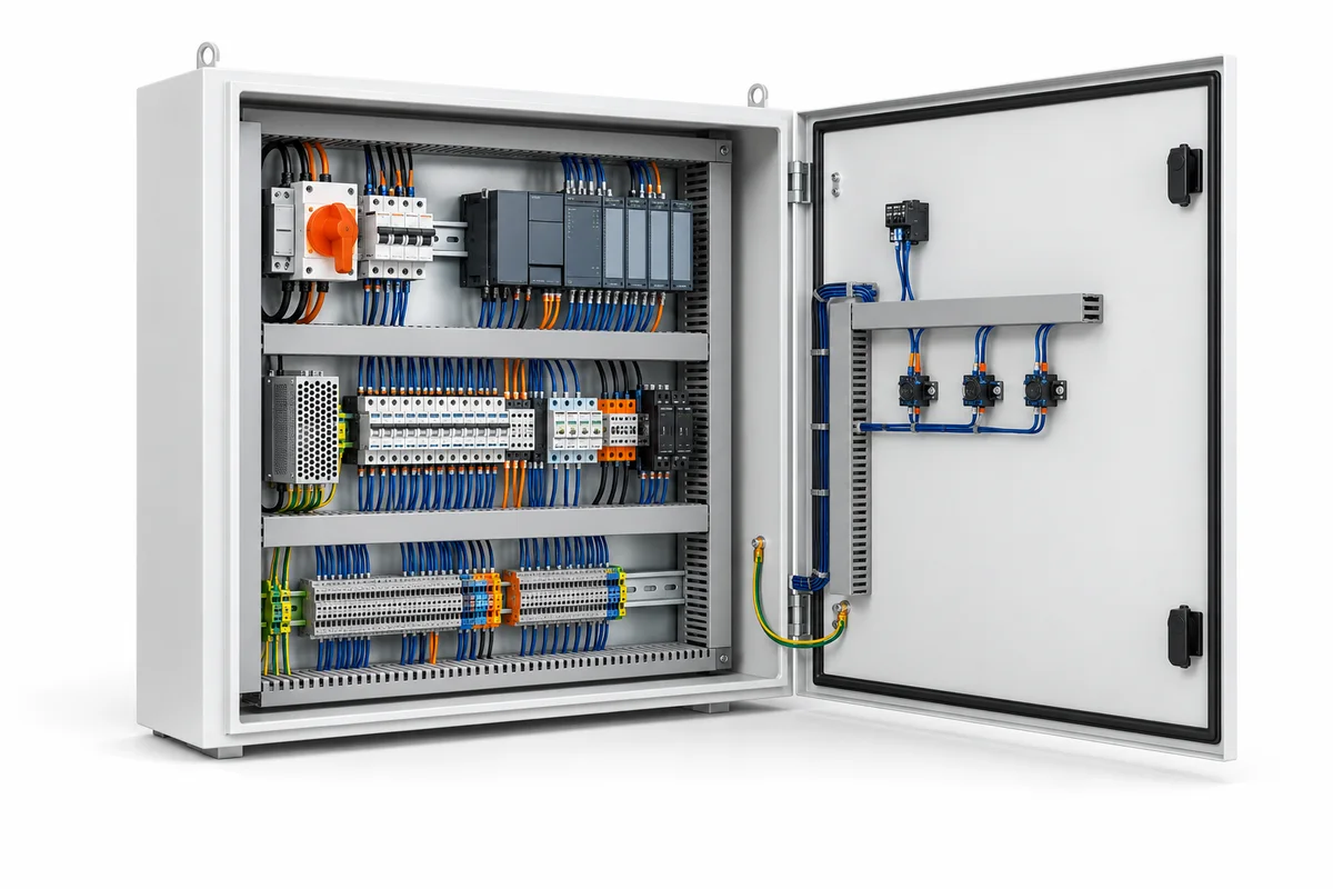
Images are AI-generated illustrations of equipment categories, not LOVATO model photographs. Confirm dimensions and ratings from the selected model datasheet.
Motor protection & control
Protect individual motor circuits as part of a coordinated starter.
Confirm: Motor full-load current · fault level · starter coordination.
Compare selection details ↗ Motor protection & control
Switch motors or other loads using the appropriate utilisation category.
Confirm: Load type and duty · coil supply · auxiliary contacts.
Compare selection details ↗ Motor protection & control
Monitor overload conditions within the motor protection scheme.
Confirm: Motor current · trip class · reset strategy.
Compare selection details ↗ Motor protection & control
Explore controlled starting for fixed-speed machinery.
Confirm: Starting torque · load inertia · bypass arrangement.
Compare selection details ↗ Motor protection & control
Match motor speed to process demand where the application permits.
Confirm: Motor current · load torque · speed range and cooling.
Compare selection details ↗ Control & signalling
Define clear local commands and machine operating modes.
Confirm: Operator function · contact blocks · ingress protection.
Compare selection details ↗ Automation & control
Define the operating sequence, inputs and operator interface together.
Confirm: I/O schedule · communications · operator screens.
Compare selection details ↗ Automation & control
Budget the control-system DC demand and start-up requirements.
Confirm: Output voltage · continuous current · inrush and derating.
Compare selection details ↗ Explore all 36 component families ↗
METHODS & WORKED EXAMPLES
Understand the estimate. These examples use the default inputs. Change the live controls above for your own scenario; the reference examples below remain fixed.
Motor starting current — worked example Example inputs Motor rating: 55 kW System voltage: 415 V — industrial Phase: 3Φ (three phase) Starting method: Direct on line (DOL) Efficiency: 92 % Power factor: 0.86 Example result Full load current: 96.7 A Starting current: 580 A Starting multiplier assumption: 6 × FLC Assumptions & limits Starting multipliers are illustrative, not measured inrush or guaranteed torque. Verify motor nameplate, load acceleration, supply limits and starts per hour. Preliminary planning only. Final selection needs project-specific engineering verification. Motor energy comparison — worked example Annual kWh = rated shaft kW × load fraction × annual hours / efficiency fraction. Cost difference uses the entered energy tariff.
Example inputs Rated shaft power: 30 kW Shaft load: 75 % Existing efficiency at duty: 88 % Replacement efficiency at duty: 93 % Annual running hours: 4000 h Energy tariff assumption: 25 KES/kWh Installed replacement cost: 150000 KES Example result Existing annual energy: 102,272.7 kWh Replacement annual energy: 96,774.2 kWh Annual cost difference: 137,463 KES Assumptions & limits Both motors deliver the same shaft duty. Use efficiency at this load, not an unrelated nameplate point. Tariff is your scenario input, not a published utility rate. Simple payback excludes finance, maintenance, downtime and tariff changes. Negative difference means higher operating cost. Preliminary planning only. Final selection needs project-specific engineering verification. Technical reference: US Department of Energy: motor systems guide . This reference does not certify the website calculation or an NPE assembly.
MCB / MCCB / ACB sizing — worked example Example inputs Load value: 160 Unit: Amps System phase: 3Φ (three phase) System voltage: 415 V — industrial Load profile: General power Fault level: 25 kA Altitude: 1700 m Ambient temperature: 35 °C Example result Nominal rating (In): 200 A Device frame: MCCB (moulded case) Tripping curve: Curve C (5–10× In) Assumptions & limits Altitude derate: 0 % at 1700 m Temperature derate: 4 % at 35 °C Load profile factor applied: 1.1× Preliminary planning only. Final selection needs project-specific engineering verification. METHODS & WORKED EXAMPLES
Understand the estimate. These examples use the default inputs. Change the live controls above for your own scenario; the reference examples below remain fixed.
DC control power budget — worked example Example inputs DC output voltage: 24 V DC PLC and other continuous load: 25 W Simultaneously held DC coils: 6 Holding power per DC coil: 3 W Simultaneous sensors: 10 Power per sensor: 0.5 W Reserve allowance: 25 % Example result Connected continuous load: 48 W Budget with reserve: 60 W DC output current budget: 2.5 A Assumptions & limits Pload = PLC / other W + coil count × holding W + sensor count × sensor W. Pbudget = Pload × (1 + reserve / 100); Ibudget = Pbudget / DC voltage. Reserve is a planning assumption, not a manufacturer requirement. All listed loads must match the selected DC voltage. AC coil VA and DC coil watts are not interchangeable. Check coil pull-in peaks, simultaneous starting, temperature and altitude derating, overload behaviour and branch protection separately. This tool does not select a supply model. Preliminary planning only. Final selection needs project-specific engineering verification. Method reference: MEAN WELL — Power supply selection FAQ
Three-phase voltage unbalance — worked example Example inputs L1–L2 voltage: 415 V L2–L3 voltage: 410 V L3–L1 voltage: 420 V Example result Average line voltage: 415 V Maximum deviation: 5 V Voltage unbalance: 1.2 % Assumptions & limits Unbalance (%) = 100 × maximum absolute deviation from the average / average. Use line-to-line readings taken under the same operating condition. No pass/fail limit or trip delay is selected. Check equipment limits and investigate supply conditions with a qualified engineer. This method uses voltage magnitudes only; it is not an IEC negative-sequence calculation. Preliminary planning only. Final selection needs project-specific engineering verification. Method reference: US DOE — Energy Management for Motor-Driven Systems